During the operation of the power station KS 5200PS, I encountered an error E03. Due to the almost complete lack of public technical information regarding this model on the internet, I contacted the manufacturer's technical support Könner & Söhnen directly, requesting clarification and documentation.
In response, the support service sent me (not immediately, I will explain this below) two technical files with a detailed description of possible connection schemes, operating modes of the station, grounding recommendations, working with generators and solar panels, as well as an explanation of the logic of mode switching.
I publish these materials exclusively for informational purposes, as at the time of writing this article, there is practically no structured and understandable documentation regarding KS 5200PS available online, especially in Ukrainian. I hope this information will be useful to other owners of this station.
My disclaimer
The materials provided below are published exclusively for familiarization.
I am not a representative of the manufacturer and do not provide official recommendations for installation or operation.
Any electrical installation work should be carried out by qualified specialists in compliance with current norms and regulations.
All decisions are made at your own risk.
Manufacturer's disclaimer (Könner & Söhnen)
This informational material is for familiarization purposes and is intended to demonstrate the functions of Könner & Söhnen products and possible applications.
All recommendations should be adapted to the specific installation conditions.
Installation must be carried out in accordance with current standards and regulations.
The manufacturer is not responsible for incorrect installation and its consequences.
I will add the content of the files below this post. And now a bit of my own experience.
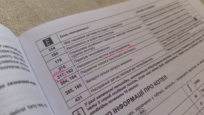
E317 and Baxi boiler
The KS5200PS station was purchased for the Baxi boiler + 2 pumps. The ability to power the entire house (lights, refrigerator, outlets) is a nice bonus.
On the very first day of use - two problems.
The boiler shows error E317
The KS5200PS station shows error E03
I installed a panel with AVR. But the boiler decided to show error E317. This is not related to this charging station. I described in more detail what the problem was and how to fix it in this post.
[Resolved / Personal experience] E03 KS5200PS
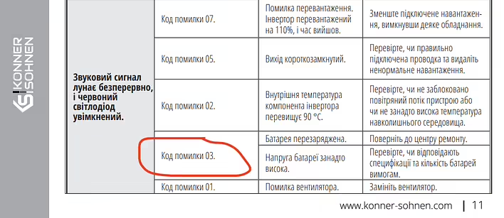
However, the error E03 is larger and more unclear. According to the documentation:
Error code 03

Battery overcharged: Return to the repair center.

or

Battery voltage too high: Check if the specifications and number of batteries meet the requirements.
Скріншот з інструкції
Sending such a heavy thing to the repair center is not an option. And the other option "Check if the specifications and number of batteries meet the requirements." doesn't really help.
In general, I probably need to describe the symptoms of E03.
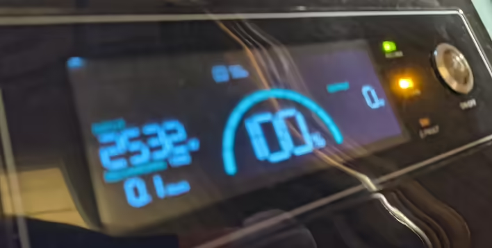
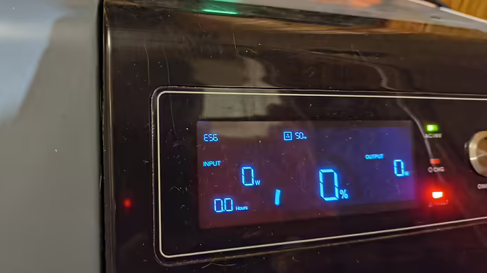
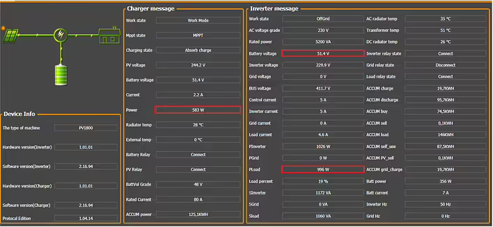
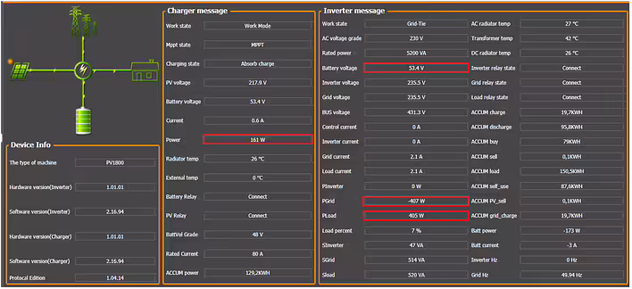
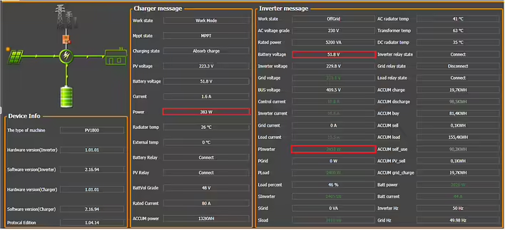
The charging station is powered from the city network
Reaches 100% -> Error E03 (red indicator blinks and loud sound signal ~ 7 times).
The station does not supply electricity because the AVR switched the house to the city. But after 10-20 minutes, it starts charging again (reminding that it shows a charge of 100%). -> error E03.
And so on in circles. The error and sound signal every 10-20 minutes.
Заряджається на 100% й йде в E03 (вибачаюсь за якість фото)
The problem here is that the station is located near the bedroom. At night, according to the blackout schedule, there should be a power outage. 3-6 hours. To keep the boiler running - you need to have backup power on. But it beeps.
Of course, the station can be disconnected from the network and it won't beep. But the next problem is that the station needs to automatically recharge after the power is restored. Running around at night/morning to switch all this is inconvenient. I also contacted technical support. Here is the first response:
Hello!
Welcome to Könner & Söhnen

To balance their operation, we recommend performing two full cycles: completely discharge the station and then fully charge it to 100%.
It is important to charge to full level, as cell balancing occurs at the final stage of charging with very small currents.
With frequent short power outages, this process sometimes does not have time to occur, so full cycles help balance all cells and eliminate the error.
If the problem persists after two cycles — write to us, and we will continue the diagnosis.
Sounds promising. We start discharging and charging.
I discharged the station for the first time to 4% and it shut down. The station was delivering 2500W. So, most likely it went into over-discharge protection. We won't count this time.
The next 3 times of discharging were (the last 10%) at the level of 250-500W. And the station shut down at 0%. And this did not help. The station still shows error E03. But judging by the problem itself (BMS / balancing) - 3 times might not have been enough.
I called technical support and received the following information:
3 times is not enough for balancing. There are many cells/batteries.
Just use the station and over time the error will disappear (but this error sound does not let me sleep. see the next point).
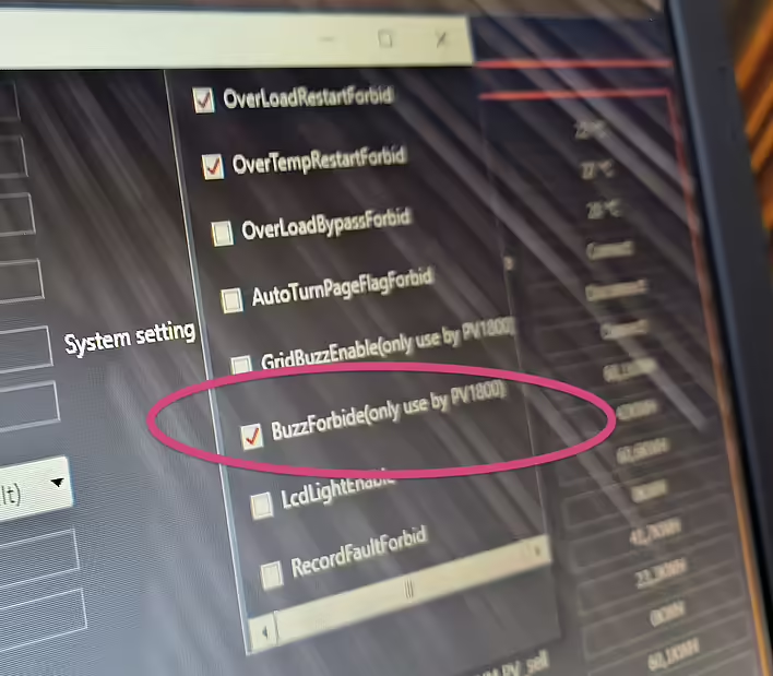
To turn off the sound signal - you need to connect to the station via wire and use a program to disable the necessary option.
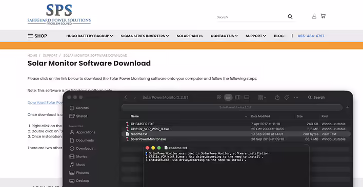
They sent me a link to the software and 2 PDF files for familiarization via Viber. The next problem arose - the software is only for Windows.
Link to the software:
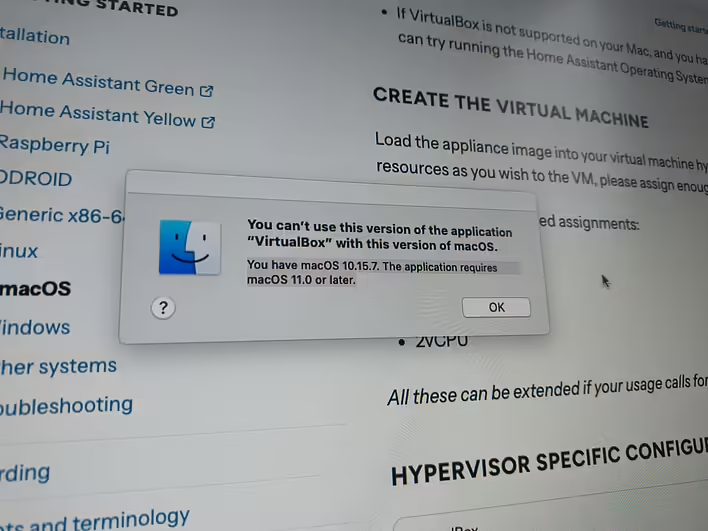
https://safeguardpowersolutions.com/support/solar-monitor-software-download/I don't have Windows and it took me a week to resolve this issue.
I'll say right away - emulators/wine/virtual machines on MacOS did not help me. Besides the software, drivers for the USB port are also needed (I couldn't overcome them). There are nuances with architecture (intel/m), and type-c/usb adapters do not work. So it turned out to be easier to find a computer with Windows.
While I was looking for one, the station was working and the error disappeared by itself (the station did not discharge to zero).
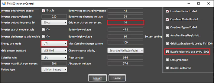
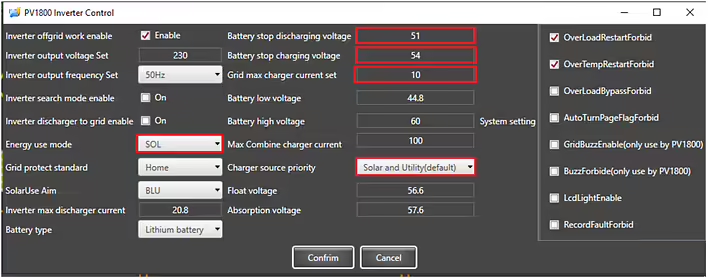
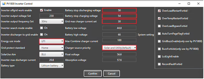
However, to prevent E03 from bothering me in the middle of the night - the sound signal was turned off in the inverter settings (BuzzForbide(only use by PV1800). I didn't change anything else. But maybe I will reduce the "Grid max charger current set" as described in the recommendations provided by technical support.
The content of the file is published unchanged. I am not responsible for the consequences of using this information.
The materials provided below are published exclusively for reference.Any electrical installation work must be carried out by qualified specialists in accordance with current standards and regulations. All decisions are made at your own risk.
Want to be prepared for power outages?
The KS 5200PS power station makes this possible both at home and in the office!The KS 5200PS can function as a solar station but also as a large portable power bank and UPS (uninterruptible power supply).
The KS 5200PS power station has an integrated LiFePO4 battery of 51.2 V 100 A*hour, which allows for the creation of an energy reserve of 5120 Wh. The inverter module of the station has a power of up to 5200 W, which is sufficient for most common consumers.
Moreover, this station has a grounded neutral, which is important for consumers such as heating boilers, etc.
The KS 5200PS provides a 230 V emergency power distribution system:
If you want to use the KS 5200PS as a UPS (for example, in case of frequent power outages or in an office with computers, etc.), we recommend powering the distribution from the backup supply through the station in constant mode.
In the office, the station can be activated only during the day if needed. It is also possible toconnect the station through a voltage control relay for additional protection.
If you plan to use the KS 5200PS station only as a backup power source, we recommend charging it, turning off the main switch on the front panel, and disconnecting it from the external AC power source using the service switch, and keeping it charged until it is needed.
In case of necessity, the KS 5200PS station is turned on using the mainswitch on the front panel, after which the backup power distribution is switched to it. We also recommend turning on the service switch so that the power station automatically switches back to the main power source after it is restored and starts charging its battery.
The inverter module and the AC source charging module of the station are activated by the mainswitch on the front panel (top right).
To turn off the station, first press the main switch, and then disconnect the AC power source (turn off the 2-pole service switch).
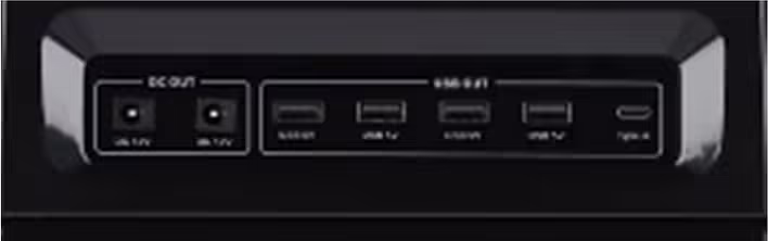
The DC outputs (12 V, USB, USB Type-C) on the front panel remain active as long as the battery switch on the back panel of the station is turned on.
Since the KS 5200PS is used in this variant without solar panels, we recommend changing the settings so that it can be charged from an external AC power source up to 100%.
Access to the settings of the KS 5200PS solar station is possible viathe SolarPowerMonitor software through an external computer.
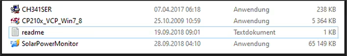
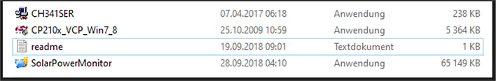
Download the Solar Power Monitor software from the link provided by the manufacturer. After unpacking, you will find 4 files:
First, you need to install the first 2 files - these are the drivers required for communication via USB. Then install the SolarPowerMonitor program.The KS 5200PS connects to the USB port of the computer using the cable included in the package. The end of the cable with USB type A connects to the computer, while the end with USB type B connects to the USB port of the power station.
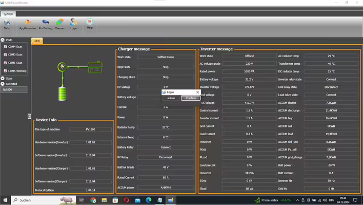
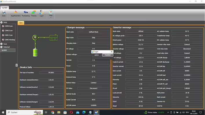
After launching, SolarPowerMonitor searches for connected stations.
As soon as the KS 5200PS is found, a window appears with its current status.
To gain full access to the settings, you need to log in with the password“admin”:
As soon as the KS 5200PS is found, a window appears with its current status. To gain full access to the settings, you need to log in with the password “admin”. Access to the inverter settings is now open:
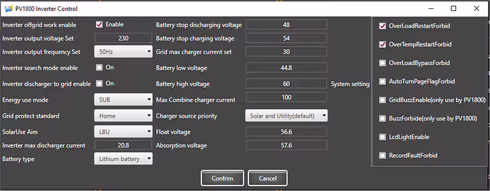
Previous settings of the KS 5200PS:
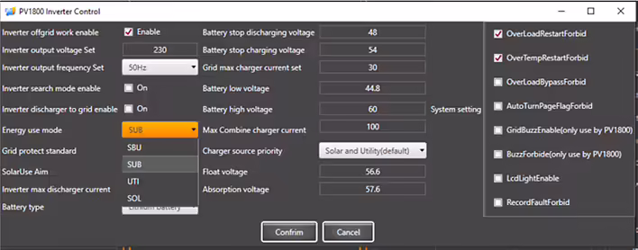
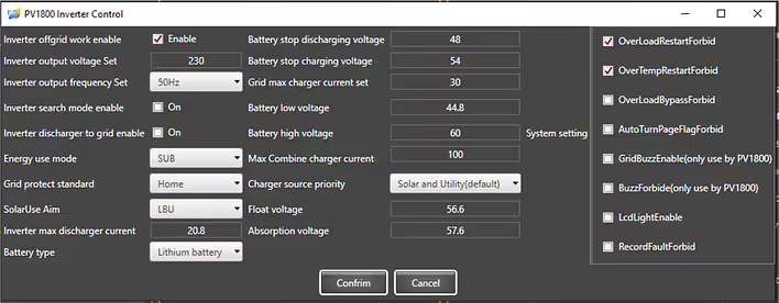
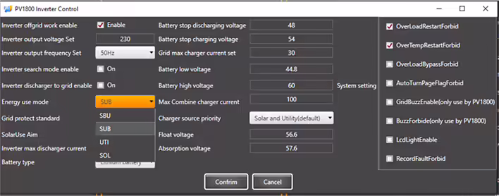
Pre-set operating mode SUB. In this mode, the internal battery of the power station is charged only from an external AC power source up to the "Battery stop charging voltage". This is approximately 60-80%, which is optimal for a longer battery life. In this mode, the battery can be charged to 100% only from solar energy. If you want the power station's battery to charge to 100% from the external grid, you need to change the operating mode to UTI.
The charging current "Grid max charger current set" for the station's battery from an externalAC power source is pre-set to 30 A (approximately 1600-1800 W charging power, full charge in about 3-4 hours), but it can be changed as needed.
Since in UTI mode the power station can be charged to 100%, during the closing of the BMS, a warning with a sound signal may occur. However, this happens quite rarely and only when you set a high charging current "Grid max charger current set". To turn off the sound signal, enable the option “BuzzForbide(only use by PV1800)”.
Note:The neutral of the AC output while operating from the battery is connected to the station's body to ensure power with a grounded neutral in the TN system. The KS 5200PS station must be connected to the grounding bus PE through the PE contacts on the AC input-output or through the grounding screw located at the bottom of the back panel.
DISCLAIMER:This informational material is intended to familiarize you with the features of Könner & Söhnen products and their application possibilities, and can only be considered as recommendations that must be adapted to the circumstances and conditions during installation.
The installation itself must be carried out in accordance with all applicable standards and regulations. We are not responsible for incorrect installations and their consequences.
The content of the file is published unchanged. I do not bear responsibility for the consequences of using this information. The materials presented below are published exclusively for informational purposes. Any electrical installation work must be carried out by qualified specialists in accordance with current norms and regulations. You make all decisions at your own risk.
Have you ever thought about getting free energy from the sun to reduce your electricity costs? Want to prepare for a possible power outage so that lights, heating, refrigerator, etc. continue to work? Want to charge your electric car with solar energy?
This is possible with the KS 5200PS solar power station!
The KS 5200PS solar power station can operate even with 4-6 panels(depending on the output voltage) and provide consumers with electricity up to 5200 W. The output voltage of the solar field under load should not be less than 150 V. The maximum voltage of the solar field is 450 V in open circuit mode and 430 V under load. The built-in MPPT charge controller can convert up to 5 kW. Solar energy is used to power consumers and is stored in the station's battery.
The KS 5200PS station is designed for stationary use. Internalrelays connect an external AC power source on bothconductors (L and N) when it is used as a power source.Internal relays disconnect the external AC power sourceon both conductors (L and N) when the station switches to off-grid mode.
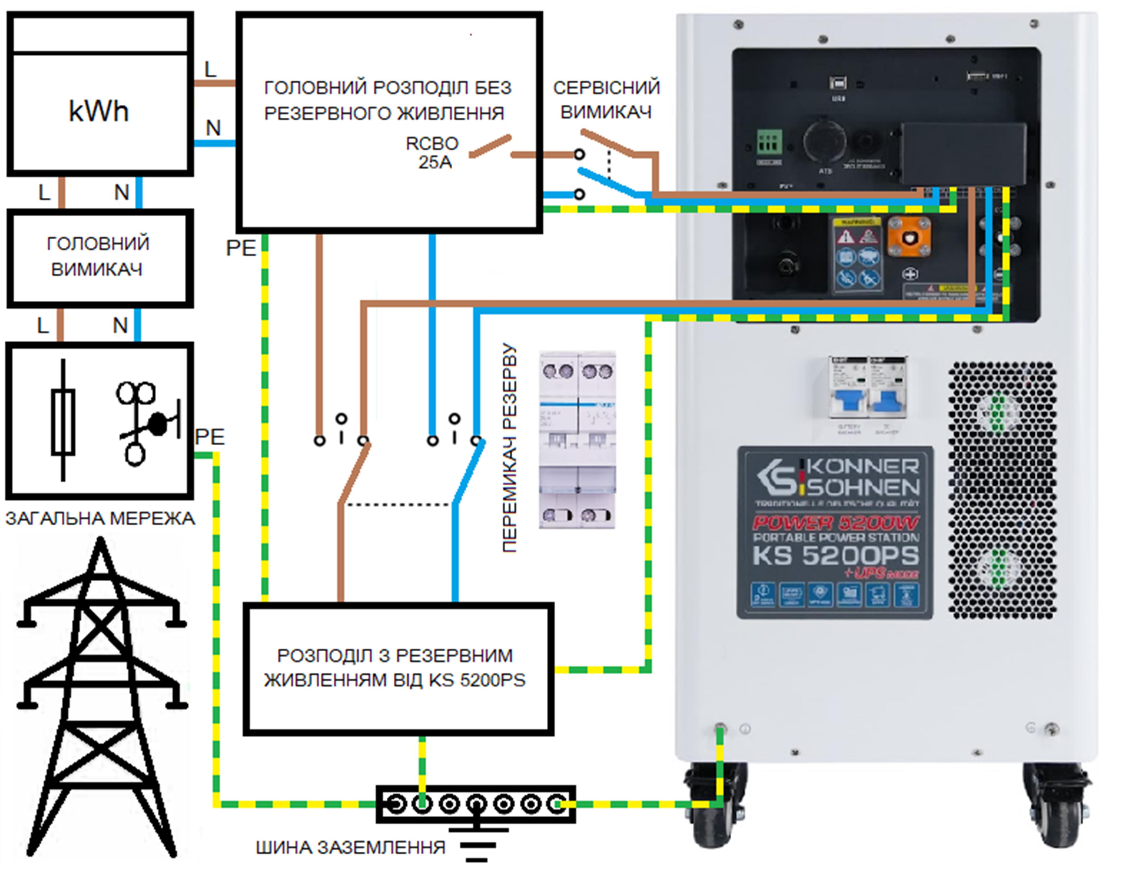
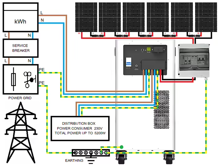
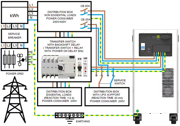
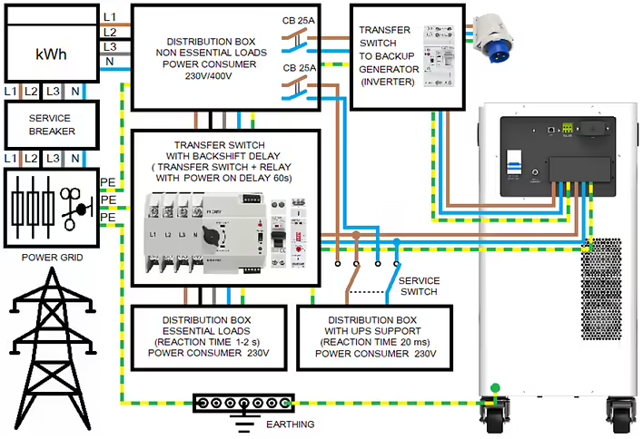
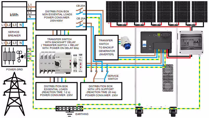
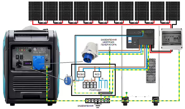
The output neutral conductor in off-grid mode is connected to PEthus grounding it to create a TN system for correctpowering of the house. Operating the station without grounding is prohibited.The recommended scheme for 1-phase power supply to the house:Modern houses usually have a 3-phase connection and consume more than 5200 W. In this case, we recommend using a scheme withconsumers divided into one group without backup power and 2 groups with backup power as shown in the diagram below.
The recommended connection scheme with backup power from KS 5200PS:
All electricity consumers in the house are divided into those without backup power and those 230V consumers that have backup power from the KS 5200PS power station with a total power of up to 5.2 kW (at cos φ = 1). When calculating consumption, it is necessary to take into account the power factor and the starting power of the consumers.
Backup power at 230 V or 400 V?
Three-phase current 400V is usually only needed for devices where arotating field is required. These are consumers with 3-phase motors.
Such consumers as electric stoves, powerful instantaneous water heaters, electric boilers, or saunas are connected to 3 phases only for the purpose of load distribution in the external network and are actually 230 V consumers that can be powered from 230 V.
Powerful electricity consumers, such as electric stoves, are usuallyconnected with a copper cable of 5 x 2.5 mm2, providing power up to 4-5 kW even when operating from 1 phase 230 V. However, we recommend not to turn on more than a couple of burners or one burner and no more than one heating element of the electric oven at the same time to prevent overload. Always consider the total power of active electricity consumers. In case of overload protection tripping, the 230 V output of the station must be reactivated by turning it off/on with the button on the front panel.
Distribution for consumers with a switching time to backup power of 1-2 sPowerful electricity consumers, such as kitchen appliances (including electric stoves), are usually powered from 3 different phases of the general power grid (with a 3-phase connection to the house). In case of a power outage, they switch to KS 5200PS. The switching time of most automatic switches is about 1-2 seconds, which should not be a problem for most devices.
Please note that some kitchen appliances, such as coffee machines, even in standby mode, occasionally turn on heating elements, which can lead to overload if you also turn on other high-power consumers. Therefore, we recommend using such powerful consumers as washing machines (require up to 2500 W), coffee machines (require up to 1500 W), dishwashers (require up to 2200 W), kettles (1200-2400 W), hot water boilers (700-2200 W) considering electricity consumption.
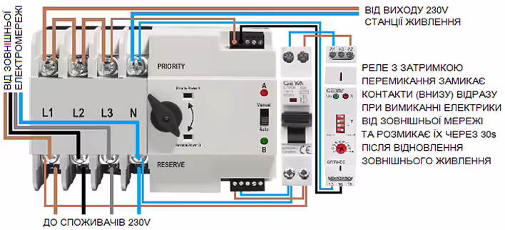
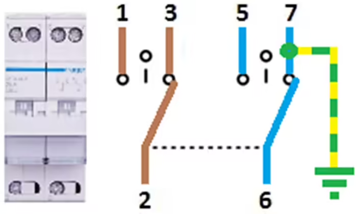
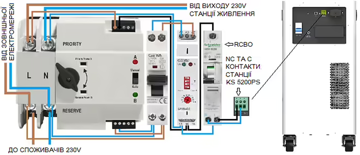
Switching block for consumers with a response time of up to 1-2 sWe recommend using an automatic switch with separately output control contacts for switching between power sources. Such switches are available on the market in various versions.
The input (in the picture above) of such an automatic switch has priority when selecting the power source output. If the priority power sourceis turned off, the switch switches to the non-priority side (often referred to as backup), if 230 V voltage is applied to the control contacts of this side. The reverse switching occurs as soon as 230V voltage is applied to the control contacts of the priority side. However, automatic switches should not switch to the general power grid immediately after power restoration, but only with a delay of at least 60 seconds after power restoration. This is ensured by a delay relay that monitors the voltage from the power grid and switches 230 V from the solar power station to the control contacts of the automatic switch when power from the external power grid is lost.
Example of a switching block with a delay for reverse switching:
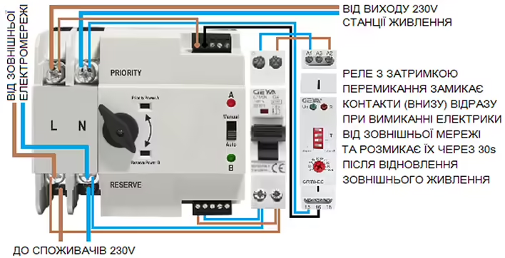
If your house is connected to only 1 phase from the external power grid:
The output of KS 5200PS is connected to the priority side, but the control contactsremain de-energized (the delay relay contacts are open) as long as there is power from the general power grid and the load power is supplied from the external network through the non-priority side. The relay closes its contacts immediately after the power from the external network is lost and the output switches to KS 5200PS, provided it is turned on.
The delay relaydisconnects the contacts 60 seconds after power restoration from the electrical network and switches the switch to the electrical network.
By turning off the automatic switch (in the picture to the left of the relay), you canforce the power to switch to the solar power station. This allows you tosimulate a power outage and test the operation of the automaticswitch.
Distribution with UPS function and service switchIf there are electricity consumers in the house that require uninterrupted operation and shorter switching time to backup power, they should be powered directly from the AC output of KS 5200PS, which provides a response time to power outages from the external network of 20 ms. This can be important for computers, servers, etc. However, we recommend powering these electricity consumers through an additional switch so that they can be switched from the AC output of the station to the general power grid if KS 5200PS needs to be turned off for any reason.
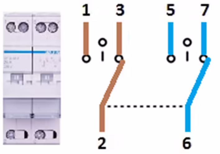
1. L (phase) from the external power grid
3. L (phase) from the AC output of KS 5200PS
5. N (neutral) from the external power grid
7. N (neutral) from the AC output of KS
5200PS
3. L (phase) to distribution with UPS function
6. N (neutral) to distribution with UPS function
If you do not have electricity consumers at home that require a UPS with a response time of 20 ms, you can provide all 230 V electricity consumers that are eligible for backup power through the aforementioned distribution with a switching time of 1-2 s.
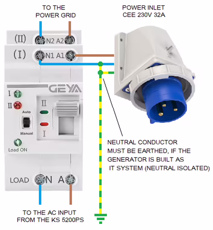
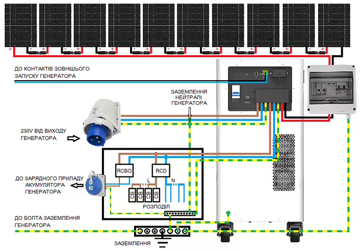
The energy stored in the station's battery is usually sufficient forseveral hours. If you want to provide power for a longer period,you must use additional energy sources, such as a backupgenerator (inverter type) or solar panels.The recommended connection scheme for a backup generator:Switching block for backup generatorThe backup generator is intended for use as a power source that may be needed in case of a prolonged power outage. It must bean inverter generator with a rated power of at least 5 kW, which is also suitable for sensitive electricity consumers and is accepted by KS 5200PS as the general power grid. The switching block must switch power from the electrical network to the generator on all poles (L and N). This can be a manual switch or an AVR module that starts the generator not immediately, but only when the control contacts of the solar power station close.
1. L (phase) from the external power grid
3. L (phase) from the inverter generator
5. N (neutral) from the external power grid
7. N (neutral) from the inverter generator
2. L (phase) to the AC input of KS 5200PS
6. N (neutral) to the AC input of KS 5200PS
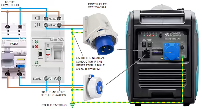
Mobile power sources are built as an IT system with isolated active conductors. The neutral conductor of the backup generator must be grounded at the switch behind the power plug. The switch switches the AC input of KS 5200PS between the public power grid (TT or TN) and the backup generator (TN) so that the power supply in the building is carried out in accordance with the rules with a grounded neutral conductor, and the distribution (this is especially important for protective disconnection devices) functions correctly.
If an external AC power source with acceptablevoltage parameters is available, KS 5200PS switches the power of consumers to this source, including the neutral, and therefore the neutral conductor of such a source must be grounded before the AC input of the station. The neutral from the external network enters the house already grounded. The neutral of the backup generator must be grounded by connecting it to the grounding of the house.
The generator remains an IT system but becomes part of the TN system as soon as it is connected to the power plug (for example, on the external wall of the house).
Switching to the emergency generator can also work automatically.
Example of a scheme with an automatic switch:
The generator is started manually
The automatic switch immediately switches to the generator as soon as it supplies voltage.
When power is restored from the electrical network, switching to the electrical network does not occur immediately, but only when the generator no longer supplies voltage, since the generator is connected to the side of the switch withpriority. To switch the power, the generator must be stopped manually.
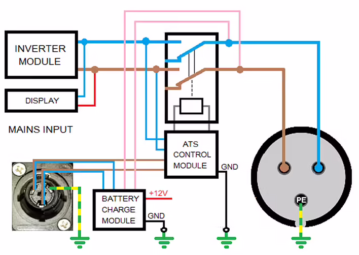
When using the inverter generator KS 6000iES ATS, automatic stopping of the generator can be implemented if the power supply from the general power grid is restored and remains stable for 1 minute.
The 230V socket at the bottom of the diagram should be protected by an overload protection automatic switch and a differential relay, or a differential automatic switch, as shown in the diagram. The cable from the 230V socket goes to the MAIN INPUT of the generator. Thus, the voltage from the power grid is monitored and the generator battery is charged so that the generator is always ready to operate. The internally installed charging module is constantly connected to the MAIN INPUT and charges the battery as needed while 230V voltage is applied to the MAIN INPUT.
The generator is started manually. For this, it is necessary to set the rotaryswitch to the RUN position and activate the ATS function. The generator detects that there is no voltage at the MAIN INPUT and starts. The generator automatically stops 1 minute after power is restored from the external network. The latest development of inverter generators from Könner & Söhnen will have a unique external control function with simultaneous monitoring of the voltage from the general power grid. Thus, 2 parameters are monitored, ensuring fully automatic operation.
The generator is started by closing the control contacts and only when there is no voltage at the MAIN INPUT. The latest version of the KS 5200PS solar power station also has an additional input for connecting a DC generator (KS 48V-DC series), making automatic battery recharging even easier. Such a DC generator can supply up to 3.3 kW to the 48V bus of the station, which can simultaneously power emergency electricity consumers in the house and charge the battery. The maximum possible load consumption current remains unchanged and corresponds to the maximum power of the station.
KS 5200PS is designed for stationary operation with a high-voltage solarfield. The neutral of KS 5200PS in off-grid mode (absence of an external AC power source with acceptable voltage parameters) is connected to PE (the casing), and the station itself must be grounded either through the PE connection at the AC input/output or through a grounding bolt on the casing.
The recommended electrical scheme with solar panels:
We recommend that when operating the station with solar panels, the SOL operating mode be set. Electricity consumers connected to the output of the KS 5200PS station switch to power from solar energy when the battery voltage reaches the "Battery stop charging voltage" value, remains at this level for 5 minutes, and solar energy is still available for 5 minutes. The output of the station switches to power from the external AC source as soon as the battery voltage drops to the "Battery stop discharging voltage" value. If more energy is coming from the sun than is needed by the electricity consumers connected to the UPS function section, other consumers can also be switched to the station using the potential-free programmable NC and C contacts of KS 5200PS.
Example of a switching block controlled by potential-free contacts of KS 5200PS:
Programmable potential-free contacts on KS 5200PS close as soon asthe battery voltage reaches the set value of "Battery stop charging voltage" andopen as soon as the battery discharges to "Battery stop discharging voltage".
The cable to the contacts of KS 5200PS must be protected by a differentialautomatic switch (RCBO), which protects against leakage and overload.
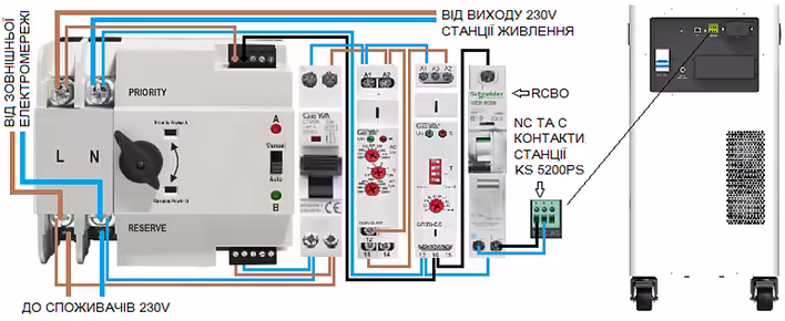
The distribution powered through the automatic switch can have voltage monitoring using a relay that opens the contacts if the input voltage goes beyond the allowable, thus activating the switching:
The automatic switch switches power to the station not only in case ofdisconnection of the external power grid but also if its voltage goes beyond the parameters set on the voltage monitor.
The voltage control relay opens its contacts as soon as the voltage goes beyond the limits set on the relay and thus activates the switching process.
The delay relay provides a delay for reverse switching to the external network.
Settings for the KS 5200PS solar power stationAccess to the settings of the KS 5200PS solar station is possible throughthe SolarPowerMonitor software via an external computer.Download the Solar Power Monitor software from the link provided by the manufacturer. After unpacking, you will find 4 files:
First, you need to install the first 2 files - these are drivers necessary for communication via USB. Then we install the SolarPowerMonitor program.KS 5200PS connects to the USB port of the computer using the cable included in the package. The end of the cable with USB type A connects to the computer, and the end with USB type B connects to the USB port of the station.
After starting SolarPowerMonitor, it searches for connected stations.
As soon as KS 5200PS is found, a window appears with its current status. To gain full access to the settings, you need to log in with the password "admin":
As soon as KS 5200PS is found, a window appears with its current status. To gain full access to the settings, you need to log in with the password "admin". Access to the inverter settings is now open:
Default settings for KS 5200PS:
The pre-set operating mode is SUB. In this mode, the internal battery of the station is charged only from the external AC power source up to the "Battery stop charging voltage" value. This is approximately 60% charge. In this mode, the battery can only be charged to 100% from solar energy through the PV input. Since KS 5200PS will be used as a backup, we recommend changing the operating mode to UTI, in which the battery can be charged to 100%.
We recommend reducing the charging current "Grid max charger current set"of the internal battery from the external AC power source to 10-20 A(approximately 550-1100 W charging power), to make more energy available for consumers when using an inverter generator as a backup power source and in the absence of solar energy. For example, smaller inverter generators with an output power of 1.8 kW or more can be used as an AC power source provided that no high-power electricity consumers or electricity consumers with large starting currents are activated in the house.
Since in UTI mode the station can be charged to 100%, a warning with a sound signal may occur during BMS closure. However, this happens quite rarely and only when you set a high charging current "Grid max charger current set". To turn off the sound signal, enable the option "BuzzForbide(only use by PV1800)".
Recommended settings for KS 5200PS for operation without solar panels:The inverter module switch 230 V on the front panel of the station must be turned on for the 230 V output of the station to operate in off-grid mode in case of disconnection from the external power grid.
Recommended settings for KS 5200PS for operation with solar panels:For operation with solar panels, we recommend setting the SOL operating mode. We recommend setting the "Battery stop discharging voltage" to 51-52V and "Battery stop charging voltage" to 54V (SOC approximately 60-80%):
We recommend leaving the "Charger source priority" setting unchanged as "Solar and utility" so that the battery can be charged to 51-52V ("Battery stop discharging voltage") from the power grid and solar energy up to 20-40% if it was discharged during a power outage, for example.
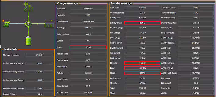
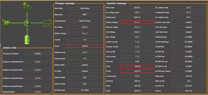
In case of a power outage, consumers are powered by the energy,stored in the battery and solar energy:
Consumers are powered from an external AC source, and the battery is charged from both the grid and solar energy until the battery voltage reaches the "Battery stop discharging voltage" value:
The output of KS 5200PS is powered from an external AC source, and the battery is charged from both it and solar energy until the battery voltage reaches the "Battery stop charging voltage" value:
If the battery voltage of the station reaches the "Battery stop charging voltage" value andsolar energy is still available for another 5 minutes, KS 5200PS switches to off-grid mode and disconnects from the external AC source:
KS 5200PS remains in off-grid mode until the battery voltage drops to the "Battery stop discharging voltage" value. Then KS 5200PS switches to the external AC power source if it is available.KS 5200PS has "dry" control contacts that can switch up to 250V 1A, and which can be used to control the generator if they are not already used for controlling the switching block.
Contacts C and NO close as soon as the battery voltage drops to the "Battery stop discharging voltage" value and open only when the battery voltage reaches the "Battery stop charging voltage" value.
If it is planned to create a power supply independent of the external power grid with KS 5200PS, we recommend setting the operating mode to UTI so that the generator can charge the battery up to 70-80% ("Battery stop charging voltage" 54V). The contacts C and NO of the station open as soon as the battery voltage reaches the "Battery stop charging voltage" value. To charge the battery faster, we recommend setting the charging current from the external power source to 30A. Thus, the generator will not run too long until KS 5200PS releases its control contacts C and NO again. We recommend setting the "Battery stop discharging voltage" value to 50V so that the generator does not start too early, but only when the SOC value of the battery reaches approx. 15-20%.
The recommended connection scheme with an inverter generator that has contacts for external START/STOP control:
The scheme applies to inverter generators that are started by closing control contacts and stopped by opening them. The control cable is connected to the potential-free contacts C and NO of the KS 5200PS station.
Generator batteries with external control contacts generally require maintaining their charge, and the socket shown in the diagramis used to connect an external charger, whichis usually supplied with such a generator. Without maintaining the charge, the generator battery will gradually discharge and may fail. This is especiallyimportant for inverter generators that have small-capacity batteries that must power the generator's electronics in standby mode.
When using generators that do not require constant battery charge maintenance, we still recommend recharging it every 1-3 months if the generator is rarely used.
Also, every 1-3 months, depending on the design, it is recommended to run the generator to flush the fuel system. It is necessary to strictly adhere to the fuel expiration date.
When using generators with AVR that monitor the main power source230V and start in case of its absence, the NC and C control contacts can be used, which close whenthe "Battery stop charging voltage" is reached and open when the voltageof the battery drops to the "Battery stop discharging voltage".
The recommended scheme with the inverter generator KS 6000iES ATS version 2:
The ATS module of the generator monitors the voltage of 230 V at MAINS INPUT inautomatic mode, starts the generator as soon as this voltage disappears, andstops it after about 1 minute as soon as 230 V is again supplied toMAINS INPUT.
KS 6000iES ATS Version 2 is built in such a way that the voltage of 230 V at itsMAINS INPUT is only monitored and not switched to the output, sothe current from the output of the KS 5200PS station does not flow through the circuit to its input.
The internal schematic diagram of the inverter generator KS 6000iES ATSVersion 2:
The CEE 230V 32A socket is connected to the output of the inverter module and is active only during the operation of the generator.
The generator is turned on (ON position) or off (OFF position) manually using a multifunction switch (gasoline tap, ignition, power of the control unit). The generator is started in manual mode using the red button on the multifunction switch.
With the ATS SWITCH, the automatic mode is turned on (ATS SWITCH inON position) or off (ATS SWITCH in OFF position).The voltage of 230 V from the output of KS 5200PS reaches MAINS INPUT of the generator through protection in the form of a differential automatic switch (RCBO) and the NC and C contacts of the KS 5200PS station, which close when the battery voltage reaches the "Battery stop charging voltage" value and open when the battery voltage drops to the "Battery stop discharging voltage" value. Thus, immediately after the station is turned on, the generator starts to charge the battery, and then turns off 1 minute after reaching the "Battery stop charging voltage".
The cable to the control contacts and to the socket must be protected fromoverload and contact (RCBO). The phase conductor from the AC output of KS 5200PS goes to the Schuko socket, and from there to MAINS INPUT of the generator. The neutral conductor goes to the control contact C, and from the control contact NC returns to the socket and from there to MAINS INPUT of the generator.
When the NC and C contacts are closed, the voltage of 230 V reaches the MAINS INPUT of the generator and powers the electronics and the battery charging module of the generator. This means that the generator is always ready to operate.
By turning off the RCBO, you can forcibly start the generator for test purposes, or if, for example, you want to recharge the station's battery in the evening so that it does not start at night when the battery voltage drops below "Battery stop discharging voltage" 50 V.
When using other generators with internal or external AVR according to the same scheme, they need to be modified, as most AVRs switch the voltage of 230V from input to output, causing current to flow in a loop from the output to the input of the station, which is unacceptable.
DISCLAIMER:This informational material aims to familiarize with the features of the productsKönner & Söhnen and the possibilities of their application, can be considered onlyas recommendations that must be adapted to the circumstances and conditions duringinstallation. The installation itself must be carried out in accordance with all applicablestandards and regulations. We do not bear any responsibility
![Post cover: [Personal Experience] How I Dealt with the E03 Error on KS 5200PS](https://d3kb0xa9zqcv9v.cloudfront.net/qbmx9gef6wz0p8kf2q49chgeyyyu)